Wednesday, July 28, 2010

The user manual for the Tetrix mill

This should explain the main functions of the Mill.

The axis description is realized by applying the (machinery) “right hand rule”:
*positive x axis is from the left to the right
*positive y axis is from the front to the back
*positive z axis is from the bottom to the top

The hardware setup:
-the Tetrix controllers are plugged in at NXT port 1
-z axis motor is on the first controller
-x&y axes are on the second controller

On every axis we have a LEGO encoder
x: NXT port 2
y: NXT port 3
z: NXT port 4
x&y have additional Tetrix encoders.
The LEGO encoders are mainly for the safety-control.

Then on the software site we have also 2 different types of vis: the difference is between the encoder type (Lego or Tetrix).
At first, I only worked with the Lego encoders, because I wanted to spend less money as possible. But after a while, I wanted to find out if the mill would be working better with higher resolution encoders. The second cause to use Tetrix encoders was to use the constant speed mode on the Tetrix vis.
At the beginning, I measured the “power to speed curve” of the motors and approximate a mathematical curve to this curve. I was able to run the motors in a proportional way so that the motions are getting smoother. About this proportional controller you can read in an earlier post.
With the Tetrix encoders the speed control is easier to manage, because the vi has the constant speed mode with allowed you to run the motors at the exact speed you need.

With the Tetrix encoder you can run the motors in two different ways: distance move or read the encoder like the Lego encoders. The main problem of the distance vi is that the controller tries in alternating the directions to reach the real encoder positions until the watchdog (which one you can setup manually) cut the motors off. This is very annoying so I decided to write the vis like the Lego encoders.

After hitting several times the borders or the end of one axis, I wrote a safety program. This program allows the different axis only to run in a box of 4"x 4"x 2". This box is controlled by the Lego encoders, which are very good for this job, because you cannot reset them during the program. The program has to run if you want to move an axis; flags control this. You have to start each time at the initial position, which is at the left for side point on the desk and at the maximum height. On the front panel of the safety program is a back to initial position switch, hitting this button the mill goes back to the beginning point.
The border control switch is, if you have to run to a position, which is out of the safety box, you have to push this button; if not the safety program is running back to his initial position.


After running the safety program you can start the B-code or the manual move vi.
This program is similar to the G-code (CNC programming) only that it is written in a spreadsheet and not text-like.
You have 7 fields to fill in: x;y;z;r;a1;a2;power.
X,y and z are the different axis in the desired inch length; r is the radius (also in inch) of the desired circle and a1 and a2 are the begin and end angle if you want an arc.
All the axis have to be 0 if you want to draw an arc or a circle. A positive radius gives you the arc in clockwise direction and the negative radius in counterclockwise.

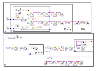
You can combine the different programs with "build an array" like you want. Here is an example of the program “draw a circle” and above CEEO. Don't forget to choose "concatenate Inputs" on the "build an array" vi.

With setting up the flag #1 the mill move back to the initial positions.

This is the movie of the program above.

Tuesday, July 27, 2010

Speed controlled circle

This is a speed-controlled circle which means that the speed of x and y are changed continuously, and so drawing a circle.
But convince yourself:


Wednesday, July 21, 2010

My Tetrix LIKE and DISLIKE list #2

This time I will focus on the Tetrix vis (software), because programming a Tetrix robot is a little trickier than a Lego one.

What are the basic issues on the Terix vis? (NEGATIVE)
1)first of all you have to find out that the Tetrix motors and servos have to be configured in a the Labview motor configurator. This is not difficult but you have to know it.
2)to use every Tetrix configuration (speed, distance) you need a encoder witch are expensive. Without the encoder you can run the motors only in the constant power mode.
3)with every program you write you have to pay attention on the watchdog and that could be very annoying.
4)if the connection (PC-NXT) breaks the motors are continuing the last command (until the watchdog stops them)
5)the "move a distance" vi is not my favorite one, it works pretty solid but the controller try to catch the exact encoder position what definitely not possible is, that makes the vi very slow because the controller tries it until the watchdog stops it. You can adjust the watchdog time direct on the vi but if you want to use the same configuration but 2 different length it is still very slow for one or the longer distance don't come until the end.


But there are still a few positive aspects on the Tetrix vis.
1)the vis are very complete, you can program a lot of things.
2)it's easy to run more motors at the same time and at different speeds (with arrays)
3)after working a while with the Tetrix vis you get used to use them correctly and it becomes as easy than the LEGO ones.


So all in all the vis are not perfect but they are useful and programmable but you have to work a little bit with them to know how to use them right, so don't be afraid....:)

Friday, July 9, 2010

Beach beast (like Theo Jansen's Strandbeest)

I'm really impressed by the "Strandbeests" which are living on dutch beaches, so I started to build one. Their "father" is Theo Jansen, please check his home page: www.strandbeest.com.

The biggest challenge was to find the right proportions between the joints and then to combine the legs to a whole robot.

The first movie shows that the beast can turn and restart walking in a synchronic manner.


The second movie shows that the beast can change his way to walk during his promenade.
The beast begins with 0 offset of the motors then it begins to change the walking mode:
1st beep: 90º motor offset
2nd beep: 180º motor offset
3rd beep: 360º motor offset


Following are the programs:
the walking mode


and the turning mode


-----------------------------------------------------------

Here is the new design of the beast:
and the Jansen mechanism:


Friday, June 25, 2010

The Tetrix (perfect) circle

Today I, or better the plotter, draw his first "perfect" circles.
It is not really a perfect circle and it would never be one. One reason is the construction used so far. Right now I use screw rods, which are first unsupported and secondly not straight. To improve the resolution of the circle, I have to buy expensive hardware, like ball-screws, bearings and encoders.
I wrote the program with the sine & cosine description of a circle, and with a proportional speed controller between both axes.
Another problem is that the motors do not start simultaneously, this cause an edge in the circle.
The proportional controller isn't accurate at all; the issue is that the motor accelerates at the beginning much faster as at the end of his power-reach. It is very difficult to find a good power-speed curve.

Next picture shows the circle drawing program:


Next are both cases for the proportional controller :


Next are both cases for the motor controller:

And of course the movie:


Next step is to engrave my name into wood...;)
Movie coming soon!

Monday, June 21, 2010

Tetrix CNC mill

This is a tough project! The aim is to build a mill to engrave letters or little signs into wood. You can find a bunch of cnc machines out of Lego, but no one can cut wood. So here is another example for what you can't build with Lego, but definitely with Tetrix.

The biggest problem is to find solutions for moving the table, because Tetrix doesn't have linear gears or something similar. This problem cannot be resolved by using Tetrix parts. So I bought 3 threat rods and 6 rod couplers for 10 $. Because Tetrix has no encoders in its basic kid and the "High Technic Encoders" are too expensive, I figured out that the "legacy angle Lego sensors" would be the best solution. Those sensors are not the most precise ones, but it would be sufficient for this application.

The next problem was about how to realize the guiding of the table. I found some interesting relations between the different profiles. But you have to try out a lot of things to find an optimal solution, because the most ideas you have, fail often on the whole relations.

The next pics show you some impressions of the construction.

The two pictures below show the guidance of the y and x direction.

Here you can see how I used the rod couplers. To use them as motor-coupler I had to bore them on the motor side up and to make a locking device.

http://www.youtube.com/watch?v=NDFuWjHLxuA

The circle has already been drawed but not filmed because it worked only once ... :)
Wood cutting and circles are coming soon....

Thursday, June 17, 2010

Ben's race car

The idea was born at lunch-time. Because I needed a ride to get some food, my colleagues were joking that I have to build a car to get there by my own. I took it for serious and constructed a car with a Tetrix kid and some NXT parts.
This is probably one of the only things you can't build with Lego.... :)


Wednesday, June 16, 2010

My Tetrix LIKE and DISLIKE list #1

LIKE:
-screws
-steel
-strength and toughness of the whole concept
-very mechanic ... :)


DISLIKE:
-the reach of the hidden screws,
(using a ball-key would help a lot)


-the keys for the small screw heads are often breaking
(lose their profile)

Here the key is stocked in the screws head.


-servo mounting is not convenient.
You can't reach the screws without dismounting the servo.
So if you want to dismount the mechanism (red screws)
You have to dismount all the green screws (5x) to reach the red screws.


-the plug of the servos works only one way
if you plug it the wrong way nothing happens, there must be a sign or another connector so that you only can plug the right way.

-the Lego to Tetrix mounting piece is in my opinion a design fail:

The only way you can fix a Lego brick is shown on the right side on the pic, but sometimes you need it in the opposite way, like it is shown on the left side. But unfortunately it doesn't fit in.

-sometimes I miss some holes...I often ask me why only every 4th big hole has 8 small holes around?

Terry's little helper Robo Tixi

The story:
Terry just had surgery and has difficulty moving around while he is recovering.

Needs of the robot:
-Follow a path (black line)
-Pick up and deliver a bottle or what ever Terry needs
-Reach Terry in a comfortable area while he is sitting (18" high)
-use only one Tetrix kid and one Mindstorms kit

Problems:
-DC motors are very strong and powerful but they have lots of friction. When you want to make a line follower you usually need slow moves, so that the common solution is to gear the wheels down.

But in my case I had a problem: the servos are very accurate but not very powerful, so if you want to lift a bottle in Terry's reach, you have to use 2 servos parallel or build a transmission. But in one kid are only 4 gears and only 2 servos (and one I need for the grapple mechanism) so I used the following configuration:
-2 wheels are coupled directly to the DC motors
-4 gears and one servo to build a strong lifter
-1 servo for the grapple mechanism

More problems:
The biggest issue was: how to reach the height with one servo?
The more you gear, the less effective angle you receive, in result you have to choose a longer lever which means bigger forces.
Which effective angle I mean? One servo can make 180 degrees, if you gear it 2:1 you receive an effective angle of 90 degrees, with a gear step 4:1 you receive an effective angle of 45 degrees.

After several tests and transmission configurations the lifter still has problems to lift a bottle (with the longest lever).
I wasn't satisfied at all and so I searched for other solutions.
2 possibilities to try:
-work with kinetic structures to increase the reach with a smaller lever
-increase the strength of the servos by changing the affect point of the forces

I went the way to help the servo to carry up the bottle with a counter weight (I took batteries and a lever). This solution was very effective.

The last problem was still existing: the friction of the motors.
While following the line, it could happen that the motors get a very low energy input (lower than the motors need to override the motor intern friction). In this case the only thing you can do is to kick the lazy robot's a... :)
No not at all the solutions are very simple: before every new power order, you have to give the motors a quick power boost.
This is the final robot:


Welcome to my blog

Hi, I'm a mechanical engineering student at a German university and right now I am working in the States (as internship) on Lego (and of course Tetrix) engineering projects.
Every one knows Lego but I guess not Tetrix.... so Tetrix is like Lego, only made out of steel.
I try to build robots with Tetrix and Lego (and if needed also with other hardwares ... :) ).
My main projects are the constructions of robots that you can't build with Lego. During the following weeks I'm going to post my issues and my realized projects on this blog.

I hope you will enjoy it ....
Have fun... :)